how to read one line electrical drawings
An electrical schematic is a diagram that shows how all of the wires and components in an electronic circuit are connected. When analyzing power grids on the transmission or distribution scale however showing each and every conductor in electrical schematic form would make the system diagram needlessly complex.

Single Line Diagram Of Power Plant Line Diagram Single Line Diagram Single Line
A one-page document it details the main components within the system and uses single lines to show how they are connected.

. Common rules help to quickly simplify the operation of complex circuits. This means each transmission or distribution power line appears as a single. You will notice that this diagram is missing the cables these can be added in without a symbol using some arrows and annotation.
Wires may cross each other on an electrical drawing but that does not necessarily mean that they connect. Basics 7 416 kV 3-Line Diagram. In this Video we have demonstrated how to read and understand electrical Single Line Diagram also called as Power Flow DiagramWe hope this video is useful.
The ability to read electrical schematics is a really useful skill to. Basics 8 AOV Elementary Block Diagram. Theyre like a map for building or troubleshooting circuits and can tell you almost everything you need to know to understand how a circuit works.
You can use a horizontal line to indicate a piece of distribution equipment such as switchgear MCC splitter or panel. The diagram also includes a summary of the wiring and electrical calculations. Basics 5 480 V MCC 1-Line.
The note Z76 indicates that the impedance of the transformer is 76. HOW TO READ A SINGLE LINE DIAGRAM. For this reason electrical power grids are most commonly represented in a single-line diagram format.
Resistors are the fundamental components of electrical schematics. Electrical plans in commercial spaces are generally drawn at the same scale as the floor plans. All points along the wire are identical and connected.
The high-voltage winding is rated 69 line to- line kilovolts kV and The low-voltage winding is rated 138 line-to-line kilovolts. Typically single line or one line diagrams are used to document the configuration of the electrical high voltage circuit of a substation. An electrical one-line diagram is a representation of a complicated electrical distribution system into a simplified description using a single line which represents the conductors to connect the components.
But you can also use the alternate rectangle symbol in the drawing. A solar one line diagram also known as a single line diagram is an electrical drawing used to design a solar PV installation. Electric Motor Controls G.
Single Line Diagram or One-line Diagram. Unless otherwise noted the impedance shown on a one-line diagram is based on the transformers OA rating. The most common scale for commercial projects is V8 l-O 1100 metric.
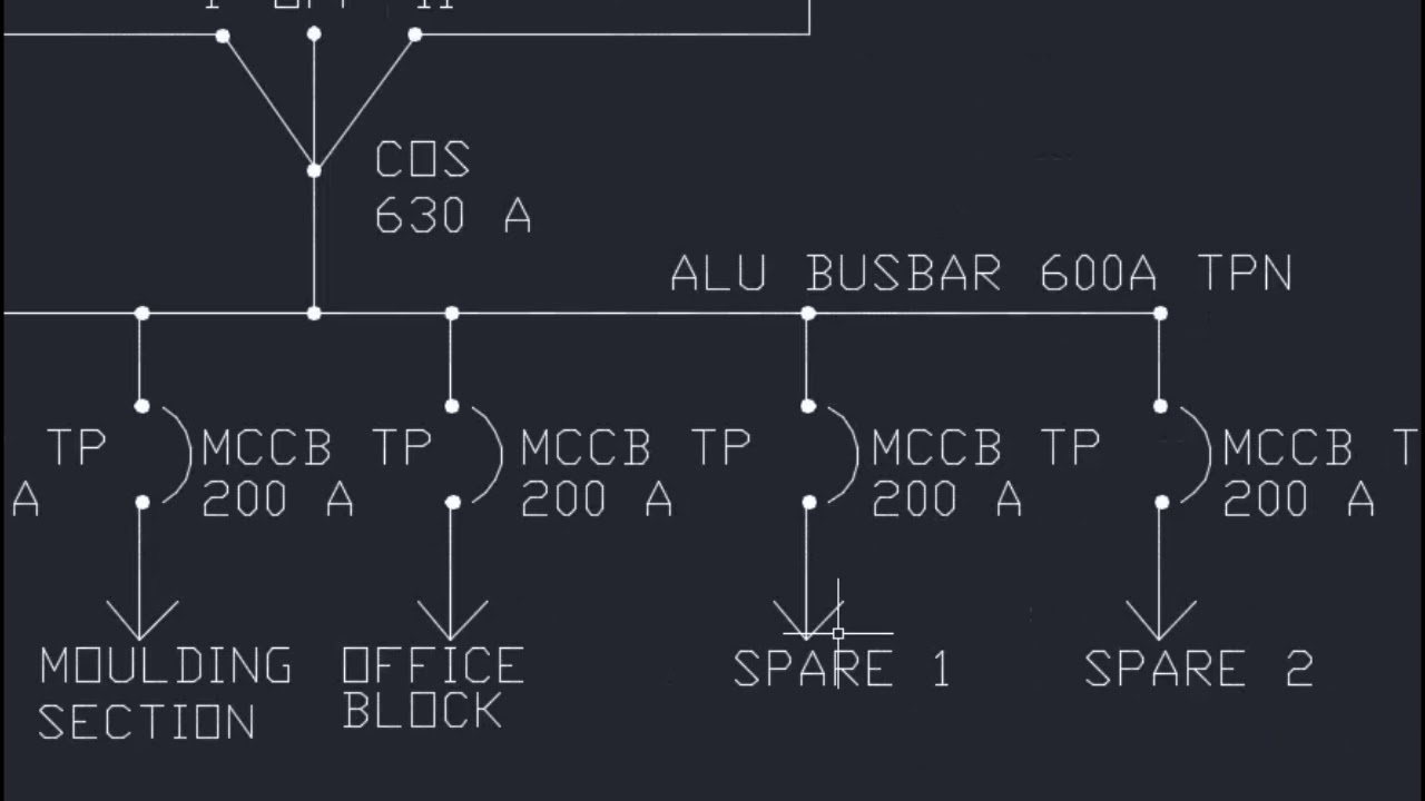
As the name suggests a single line is used to denote the multiple power lines such as in 3 phase system. Main components such as transformers switches and breakers are indicated by their standard graphic symbol. Starting at the top you will notice that a.
A one-line diagram or single-line diagram is a simplified notation for representing an electrical system. 20 rows How to read one-line diagrams. Transformers generators circuit breakers fuse air break switches reactors capacitors instrument transformers and other electrical equipment.
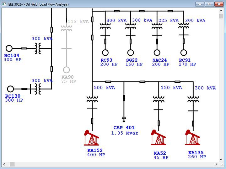
Figure 2Circuit drawing Line diagram. 31 rows Now lets go through a industrial single line diagram. Symbols are used to depict the high voltage equipment including.
Diagrams show the electrical path device wiring and sequence of operation device relationship or connections and hookups of the electrical installation. Physical relationships are typically disregarded in a single-line diagram however they should show all of the major components in the power system and list all important ratings. Each line in a line diagram should be numbered starting with the top line and reading down.
Basics 4 600 V 1-Line. The one-line diagram is similar to a block diagram except that electrical elements such as switches circuit breakers transformers and capacitors are shown by standardized schematic symbols. They are usually represented by zig-zag lines with two terminals extending outward.
Here are some of the standard and basic symbols for various components for electrical schematics. Basics 6 72 kV 3-Line Diagram. Also called one-line diagrams these drawings show the flow of electrical power or the course of electrical circuits and how they are connected.
However in complex installations the scale might be increased to V4 l-O 150 metric. Rockis 2001 Numerical Cross-Reference Systems Numerical cross-reference systems are required to trace the action of a circuit in complex line diagrams. Single Line diagram SLD or one-line diagram is the representation of an electrical circuit using a single line.
We begin with a basics fuel pump relay diagram. Basics 3 416 kV Bus 1-Line. Electrical Diagrams Electrical Layouts plans Electrical Schedules.
If they do not connect one will be shown looping around the other in a semicircle. Basics 9 416 kV Pump Schematic. To start connect your electrical symbols using one line.
First you should know the common symbols used in an sld. Basics 11 MOV Schematic with Block included Basics 12 12-208 VAC Panel Diagram. Basics 10 480 V Pump Schematic.
If they do connect they will cross and a dot will be seen at the point where the lines cross. Electrical drawings as per their purposes usually divide to main types as follows.

Simple Solar Panel Wiring Diagram The Site That This Belongs To Is Very Informative And Is A Good Read For Those Single Line Diagram Line Diagram Solar Power

Electrical Wiring Diagrams For Air Conditioning Systems Part One Electrical Knowhow Electrical Wiring Diagram Electrical Diagram Diagram
Reading Single Line Diagram Youtube

New Single Line Diagram Symbols Diagram Wiringdiagram Diagramming Diagramm Visuals Visualisation Gra Electrical Wiring Diagram Ladder Logic Line Diagram
Piping And Instrumentation Documents Instrumentation Tools Single Line Diagram Piping And Instrumentation Diagram Line Diagram
Intelligent Electrical Single Line Diagram Etap

Electrical Single Line Diagram Single Line Diagram Line Diagram House Wiring

Electrical Single Line Diagram Part Two Electrical Knowhow

Electrical Single Line Diagram Part Two Electrical Knowhow

The 16 Best Basic House Wiring Diagram References Https Bacamajalah Com The 16 Best Basic House Wi House Wiring Electrical Wiring Electrical Wiring Diagram

Pin On Follow Me On Social

New Single Line Diagram Symbols Diagram Wiringdiagram Diagramming Diagramm Visuals Visualisation Graphical Check More At Https Thebrontes Co Eletricista

Electrical Wiring Diagrams For Air Conditioning Systems Part One Electrical Knowhow Electrical Wiring Diagram Basic Electrical Wiring Ac Wiring

Learn To Read And Understand Single Line Diagrams And Wiring Diagrams Single Line Diagram Line Diagram Learn To Read

How To Map House Electrical Circuits Electrical Wiring Home Electrical Wiring Electrical Layout

Schematic Symbols Electrical Circuit Symbols Electrical Wiring Diagram Electrical Diagram

Example One Line Or Single Line Diagram Line Diagram Single Line Diagram Diagram

Electrical Wiring Diagrams For Air Conditioning Systems Part One Electrical Knowhow Electrical Wiring Diagram Circuit Diagram Electrical Symbols

Electrical Single Line Diagram Part Two Electrical Knowhow